As long as I can get the thing to work initially, I can resolve later issues with components burning out or overheating.
Thanks!!!!
Take care, Joe.

Personal computing discussed
Moderators: askfranklin, renee, emkubed, Captain Ned
notfred wrote:For hooking it up I'd be concerned about the AC flowing through the controller, I think it would be better to add the equivalent of C2 from the Relco circuit.
notfred wrote:For hooking it up I'd be concerned about the AC flowing through the controller, I think it would be better to add the equivalent of C2 from the Relco circuit.
notfred wrote:104K is 0.1uF +-10% http://jswatson.net/electronics/CapConv.html
The 2A is probably temperature and voltage rating but finding which particular chart is used could be tricky. In your case I'd just go to 400V or maybe even the next one up given 385V output from the circuit.
liquidsquid wrote:
What worries me is modern trains on this system discharging HV spikes into the motors and potentially static sensitive controllers in the engines. Not the best thing to do to sensitive electronics.
For fun when I get home I will throw together an LTSpice simulation, but I am swamped.
anotherengineer wrote:
jprampolla wrote:Ah, that's modern stuff for me, most of my motors are derivations on http://www.tri-ang.co.uk/OONew/X04.htm or http://www.tri-ang.co.uk/OONew/chassisB ... rBogie.htmThe motors in my equipment are very simple DC can motors, not expensive, and there isn't any kind of circuit, not even a diode or a capacitor, just the motor connected to wheel contacts, or wheels and center rail wipers for the 3 rail O gauge.
notfred wrote:jprampolla wrote:Ah, that's modern stuff for me, most of my motors are derivations on http://www.tri-ang.co.uk/OONew/X04.htm or http://www.tri-ang.co.uk/OONew/chassisB ... rBogie.htmThe motors in my equipment are very simple DC can motors, not expensive, and there isn't any kind of circuit, not even a diode or a capacitor, just the motor connected to wheel contacts, or wheels and center rail wipers for the 3 rail O gauge.
I'm surprised you say there is no capacitor in there, my old ones have a cap that I think is meant to stop them acting as a spark-gap transmitter and just coincidentally will help short out the oscillator in the Relco.


Version 4
SHEET 1 2116 680
WIRE 784 -288 592 -288
WIRE 784 -240 784 -288
WIRE 80 -224 -32 -224
WIRE 944 -224 832 -224
WIRE 368 -192 208 -192
WIRE 528 -192 368 -192
WIRE 592 -192 592 -288
WIRE 592 -192 528 -192
WIRE 848 -176 832 -176
WIRE 208 -160 208 -192
WIRE 368 -160 368 -192
WIRE 848 -144 848 -176
WIRE -288 -128 -304 -128
WIRE -176 -128 -288 -128
WIRE 80 -128 80 -144
WIRE 80 -128 -176 -128
WIRE -288 -112 -288 -128
WIRE -176 -112 -176 -128
WIRE 944 -112 944 -144
WIRE 80 -96 80 -128
WIRE 784 -96 784 -160
WIRE 784 -96 672 -96
WIRE 784 -80 784 -96
WIRE 816 -80 784 -80
WIRE 208 -64 208 -80
WIRE 368 -64 368 -96
WIRE 368 -64 208 -64
WIRE 528 -64 368 -64
WIRE 592 -64 528 -64
WIRE 784 -48 784 -80
WIRE -176 -32 -176 -48
WIRE 672 -32 672 -96
WIRE -288 0 -288 -32
WIRE 80 32 80 -16
WIRE 592 64 592 -64
WIRE 672 64 672 32
WIRE 784 64 784 32
WIRE 784 64 672 64
WIRE 784 80 784 64
WIRE 80 112 80 96
WIRE -32 160 -32 -224
WIRE -16 160 -32 160
WIRE 592 176 592 144
WIRE 80 208 80 192
WIRE 80 208 48 208
WIRE -16 256 -32 256
WIRE 80 256 80 208
WIRE 80 352 80 320
WIRE -32 480 -32 256
WIRE 80 480 80 432
FLAG 80 480 0
FLAG 528 -192 TRAX_P
FLAG 528 -64 TRAX_N
FLAG -32 480 0
FLAG -176 -32 0
FLAG -288 0 0
FLAG 592 176 0
FLAG 784 80 0
FLAG 944 -112 0
FLAG 848 -144 0
FLAG 816 -80 MOTOR_P
SYMBOL npn 48 160 M0
WINDOW 3 56 68 Invisible 2
WINDOW 38 56 96 Left 2
SYMATTR Value ""
SYMATTR SpiceModel bu406
SYMATTR InstName Q1
SYMBOL ind2 64 -112 R0
SYMATTR InstName L1
SYMATTR Value 30µ
SYMATTR Type ind
SYMBOL ind2 64 -240 R0
SYMATTR InstName L2
SYMATTR Value 120µ
SYMATTR Type ind
SYMBOL ind2 224 -176 M0
SYMATTR InstName L3
SYMATTR Value 1000µ
SYMATTR Type ind
SYMBOL cap 64 32 R0
SYMATTR InstName C1
SYMATTR Value 10nF
SYMBOL res 64 96 R0
SYMATTR InstName R1
SYMATTR Value 1.5K
SYMBOL diode 96 320 R180
WINDOW 0 24 64 Left 2
WINDOW 3 24 0 Left 2
SYMATTR InstName D1
SYMATTR Value 1N4148
SYMBOL res 64 336 R0
SYMATTR InstName R2
SYMATTR Value 4.7K
SYMBOL cap 352 -160 R0
SYMATTR InstName C2
SYMATTR Value 1nF
SYMBOL cap -192 -112 R0
SYMATTR InstName C3
SYMATTR Value 10n
SYMBOL voltage -288 -128 R0
WINDOW 123 0 0 Left 2
WINDOW 39 0 0 Left 2
SYMATTR InstName V1
SYMATTR Value 16
SYMBOL voltage 592 48 R0
WINDOW 123 0 0 Left 2
WINDOW 39 0 0 Left 2
SYMATTR InstName V2
SYMATTR Value 16V
SYMBOL ind 800 48 R180
WINDOW 0 36 80 Left 2
WINDOW 3 36 40 Left 2
SYMATTR InstName L4
SYMATTR Value 1000µ
SYMATTR SpiceLine Rser=10
SYMBOL sw 784 -144 R180
SYMATTR InstName S1
SYMATTR Value MySwitch
SYMBOL voltage 944 -240 R0
WINDOW 123 0 0 Left 2
WINDOW 39 0 0 Left 2
SYMATTR InstName V3
SYMATTR Value PULSE(1 0 10m 1n 1n 1m 25m)
SYMBOL cap 656 -32 R0
SYMATTR InstName C4
SYMATTR Value 1n
TEXT 1200 -72 Left 2 !**************************************\n*      Model Generated by MODPEX     *\n*Copyright(c) Symmetry Design Systems*\n*         All Rights Reserved        *\n*    UNPUBLISHED LICENSED SOFTWARE   *\n*   Contains Proprietary Information *\n*      Which is The Property of      *\n*     SYMMETRY OR ITS LICENSORS      *\n*    Modeling services provided by   *\n* Interface Technologies www.i-t.com *\n**************************************\n.MODEL bu406 npn\n+IS=3.31042e-11 BF=40.9297 NF=0.85 VAF=23.6173\n+IKF=9.89434 ISE=4.75e-12 NE=3.46875 BR=2.17748\n+NR=1.5 VAR=19.8032 IKR=10 ISC=3.25e-12\n+NC=3.65625 RB=2.68547 IRB=0.101586 RBM=0.1\n+RE=0.0001 RC=0.198649 XTB=0.128676 XTI=1.18913\n+EG=1.17512 CJE=6.29276e-10 VJE=0.651734 MJE=0.35309\n+TF=4.49798e-09 XTF=1.35722 VTF=0.995767 ITF=0.999981\n+CJC=2.66401e-10 VJC=0.409483 MJC=0.371615 XCJC=0.803125\n+FC=0.533467 CJS=0 VJS=0.75 MJS=0.5\n+TR=1e-07 PTF=0 KF=0 AF=1\n* Model generated on Jan 31, 2004\n* Model format: SPICE3
TEXT 254 448 Left 2 !.tran 100m startup
TEXT 400 104 Left 2 ;Train Power
TEXT 88 -264 Left 2 !K1 L1 L2 L3 1
TEXT 816 0 Left 2 ;Motor inductance
TEXT 1008 -192 Left 2 ;Track Fault
TEXT 1200 616 Left 2 !.model MySwitch SW(Ron=.1 Roff=1Meg Vt=0.5 Vh=-.25)
liquidsquid wrote:Spoilsport! Nobody would get their fingers zapped that wayIt needs a means to only turn on when there is a load on V2 (motor present) and turn off when there is not with some delay to differentiate between dirt and no train.
liquidsquid wrote:As promised, here is the simulation of the circuit.
The circuit needs some enhancements to limit the output voltage, and to protect Q1 from damage. It is a little too simple, but at the time of design, this was how designs were done. It needs a means to only turn on when there is a load on V2 (motor present) and turn off when there is not with some delay to differentiate between dirt and no train.
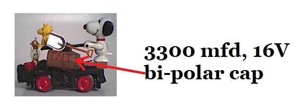
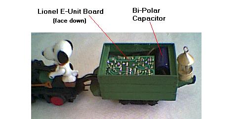
liquidsquid wrote:Another trick you could employ is use some larger bipolar electrolytic capacitors inside of the engines and other motorized devices that will keep the motors running long enough to get over the dirty spots. The capacitor needing charge after a dirty spot will certainly wet the track. If you can fit it in there. Values in the 4700uF range would be adequate. Bipolar is a must though as most electrolytics cannot be connected backwards without serious problems, like the train car blowing up.