Personal computing discussed

Moderators: askfranklin, renee, emkubed, Captain Ned

 
jprampolla
Gerbil
Posts: 48
Joined: Mon Jun 24, 2013 9:57 am
Location: USA
Contact:

Re: Replacement for BD230 Transistor?

Tue Jun 25, 2013 10:44 pm

As long as I can get the thing to work initially, I can resolve later issues with components burning out or overheating.

Thanks!!!!

Take care, Joe.
Last edited by jprampolla on Thu Jun 27, 2013 8:16 pm, edited 1 time in total.
 
notfred
Maximum Gerbil
Topic Author
Posts: 4610
Joined: Tue Aug 10, 2004 10:10 am
Location: Ottawa, Canada

Re: Replacement for BD230 Transistor?

Wed Jun 26, 2013 8:39 am

For hooking it up I'd be concerned about the AC flowing through the controller, I think it would be better to add the equivalent of C2 from the Relco circuit.
 
jprampolla
Gerbil
Posts: 48
Joined: Mon Jun 24, 2013 9:57 am
Location: USA
Contact:

Re: Replacement for BD230 Transistor?

Wed Jun 26, 2013 8:43 am

Hi Folks,

I think my choice of transistor is not a good substitute for the BD137. I think I need some help here if anyone has the time. Data sheet for the BD137: http://rfkits.com/parts/BD139-16.pdf It's the "transition frequency" that I guess is critical?

Thanks, Take care, Joe.
 
jprampolla
Gerbil
Posts: 48
Joined: Mon Jun 24, 2013 9:57 am
Location: USA
Contact:

Re: Replacement for BD230 Transistor?

Wed Jun 26, 2013 8:45 am

notfred wrote:
For hooking it up I'd be concerned about the AC flowing through the controller, I think it would be better to add the equivalent of C2 from the Relco circuit.


Thanks for the tip! I will try to ask if anyone in the Plate Layers group ever made one and used it.

Take care, Joe.
 
jprampolla
Gerbil
Posts: 48
Joined: Mon Jun 24, 2013 9:57 am
Location: USA
Contact:

Re: Replacement for BD230 Transistor?

Wed Jun 26, 2013 9:06 am

Looks like these are my only choices:

NTE 2513 http://www.onlinecomponents.com/datashe ... Resource=1
NTE 2524 http://www.onlinecomponents.com/datashe ... Resource=1
NTE 2526 http://www.onlinecomponents.com/datashe ... Resource=1

I don't understand the other parameters. Guess the heatsink needs to be a different size.

Thanks, Take care, Joe.

Please disregard the above, been resolved, new transistor BD137G and available!
Last edited by jprampolla on Wed Jun 26, 2013 1:13 pm, edited 1 time in total.
 
jprampolla
Gerbil
Posts: 48
Joined: Mon Jun 24, 2013 9:57 am
Location: USA
Contact:

Re: Replacement for BD230 Transistor?

Wed Jun 26, 2013 9:48 am

notfred wrote:
For hooking it up I'd be concerned about the AC flowing through the controller, I think it would be better to add the equivalent of C2 from the Relco circuit.


In your Relco diagram, the value of the C2 , is that 10 mfd, 2A ? What do I look for in terms of max voltage?

Thanks, Take care, Joe.
 
notfred
Maximum Gerbil
Topic Author
Posts: 4610
Joined: Tue Aug 10, 2004 10:10 am
Location: Ottawa, Canada

Re: Replacement for BD230 Transistor?

Wed Jun 26, 2013 11:51 am

104K is 0.1uF +-10% http://jswatson.net/electronics/CapConv.html
The 2A is probably temperature and voltage rating but finding which particular chart is used could be tricky. In your case I'd just go to 400V or maybe even the next one up given 385V output from the circuit.
 
anotherengineer
Gerbil Jedi
Posts: 1688
Joined: Fri Sep 25, 2009 1:53 pm
Location: Northern, ON Canada, Yes I know, Up in the sticks

Re: Replacement for BD230 Transistor?

Wed Jun 26, 2013 12:05 pm

Are you sure this isn't your wiring diagram ;)

https://xkcd.com/730/
Life doesn't change after marriage, it changes after children!
 
liquidsquid
Minister of Gerbil Affairs
Posts: 2661
Joined: Wed May 29, 2002 10:49 am
Location: New York
Contact:

Re: Replacement for BD230 Transistor?

Wed Jun 26, 2013 12:21 pm

A quick interpretation of the design is a simple flyback self-oscillating boost circuit. It adds some low-current HV AC on top of the controlling high-current DC voltage.

With a heavy load, the oscillation dampens (when train is in contact with rail, oscillator is "shorted" and produces nxt to nothing), but when the load opens up such as when the motor loses contact with the rail because of dirt, smudge, etc, the oscillator begins and ramps up the voltage to fairly high levels until an arc forms and either blasts the dirt or builds up again until a contact is made. Because it is self-oscillating, the voltage can ramp pretty high, higher than the turns ratio suggests. You may achieve up to 1KV or more on the secondary. That is why the one circuit has a neon bulb: to prevent the output from going too high. That limits it to around 100V or so.

What worries me is modern trains on this system discharging HV spikes into the motors and potentially static sensitive controllers in the engines. Not the best thing to do to sensitive electronics.

It likely oscillates in the 10's of kHz max due to the iron core slowing things down. It is probably a custom wound coil for the application, since the coil connected to the base of the transistor likely has about 1/10 the windings of the coil connected to the collector. You only need a little more than 0.7 volts induced on the base to turn the transistor on, then current takes over, not voltage.

This type of circuit is very touchy, and requires specific gains on the transistor, but I don't know of a transistor that is slow enough to be a problem here. Any frequency rating will do that is in that package. You are interested in gain (hFE) being at least the same or higher, Voltage being same or higher, and heat dissipation being same or higher. Lots of parts out there for that, but a good NPN with more than enough goods to do the job is: BU406. More than enough V, and power rating is decent. You will be hard-pressed to kill it again.

Note as the neon bulb ages, the breakdown voltage goes up. That may have lead to the demise of your board, and continue to lead to the demise. You may be better-served by replacing the transistor and then the Neon bulb with a bi-directional TVS like those from Littlefuse. You can pick just about any voltage you wish to limit things to.

For fun when I get home I will throw together an LTSpice simulation, but I am swamped.
 
liquidsquid
Minister of Gerbil Affairs
Posts: 2661
Joined: Wed May 29, 2002 10:49 am
Location: New York
Contact:

Re: Replacement for BD230 Transistor?

Wed Jun 26, 2013 12:23 pm

Oh, and as far as motor efficiencies: Those rare-earth magnets are amazing compared to what was in old DC motors. The energy density of the DC motor magnet governs efficiency and motor size.
 
jprampolla
Gerbil
Posts: 48
Joined: Mon Jun 24, 2013 9:57 am
Location: USA
Contact:

Re: Replacement for BD230 Transistor?

Wed Jun 26, 2013 12:39 pm

notfred wrote:
104K is 0.1uF +-10% http://jswatson.net/electronics/CapConv.html
The 2A is probably temperature and voltage rating but finding which particular chart is used could be tricky. In your case I'd just go to 400V or maybe even the next one up given 385V output from the circuit.


Thanks, I think I already have some of approx. that rating from an old project which was an HF AC lighting circuit.

BTW, the tech support at the vendor in the link above (top of the page) told me that the transistor now has a "G" suffix but is the same, so that's resolved.

Also, thanks for that capacitor link!!!!

When I use this circuit, I will have 2 separate wall warts for the power supplies. So for track power, it will be a fixed voltage 7 VDC wall wart and I use a little extra polychem circuit breaker on the line, although I know that probably won't help with the HF AC getting back to the wall wart. I will put the cap in parallel with the little wall wart. Probably saved me from a little explosion!

Take care, Joe
Last edited by jprampolla on Wed Jun 26, 2013 4:42 pm, edited 2 times in total.
 
jprampolla
Gerbil
Posts: 48
Joined: Mon Jun 24, 2013 9:57 am
Location: USA
Contact:

Re: Replacement for BD230 Transistor?

Wed Jun 26, 2013 12:54 pm

liquidsquid wrote:

What worries me is modern trains on this system discharging HV spikes into the motors and potentially static sensitive controllers in the engines. Not the best thing to do to sensitive electronics.

For fun when I get home I will throw together an LTSpice simulation, but I am swamped.


Please don't go to any more trouble on my behalf. The motors in my equipment are very simple DC can motors, not expensive, and there isn't any kind of circuit, not even a diode or a capacitor, just the motor connected to wheel contacts, or wheels and center rail wipers for the 3 rail O gauge.

I am assuming that I can get the thing working well enough to see if there is an issue with the "sintered" metal wheels and tin plated track.

My biggest problem is in knowing terminology and finding the mylar and polystyrene substitutes for the caps, etc.

Unless I missed something, there isn't a neon bulb in the circuit I am trying to build.

Thanks,Take care, Joe.
 
jprampolla
Gerbil
Posts: 48
Joined: Mon Jun 24, 2013 9:57 am
Location: USA
Contact:

Re: Replacement for BD230 Transistor?

Wed Jun 26, 2013 1:04 pm

anotherengineer wrote:
Are you sure this isn't your wiring diagram ;)

https://xkcd.com/730/

Thanks, enjoyed that diagram/schematic very much! Think I will need some holy water when I test it! :lol:

Take care, Joe.
 
notfred
Maximum Gerbil
Topic Author
Posts: 4610
Joined: Tue Aug 10, 2004 10:10 am
Location: Ottawa, Canada

Re: Replacement for BD230 Transistor?

Wed Jun 26, 2013 1:26 pm

jprampolla wrote:
The motors in my equipment are very simple DC can motors, not expensive, and there isn't any kind of circuit, not even a diode or a capacitor, just the motor connected to wheel contacts, or wheels and center rail wipers for the 3 rail O gauge.
Ah, that's modern stuff for me, most of my motors are derivations on http://www.tri-ang.co.uk/OONew/X04.htm or http://www.tri-ang.co.uk/OONew/chassisB ... rBogie.htm
I'm surprised you say there is no capacitor in there, my old ones have a cap that I think is meant to stop them acting as a spark-gap transmitter and just coincidentally will help short out the oscillator in the Relco.
 
jprampolla
Gerbil
Posts: 48
Joined: Mon Jun 24, 2013 9:57 am
Location: USA
Contact:

Re: Replacement for BD230 Transistor?

Wed Jun 26, 2013 1:47 pm

notfred wrote:
jprampolla wrote:
The motors in my equipment are very simple DC can motors, not expensive, and there isn't any kind of circuit, not even a diode or a capacitor, just the motor connected to wheel contacts, or wheels and center rail wipers for the 3 rail O gauge.
Ah, that's modern stuff for me, most of my motors are derivations on http://www.tri-ang.co.uk/OONew/X04.htm or http://www.tri-ang.co.uk/OONew/chassisB ... rBogie.htm
I'm surprised you say there is no capacitor in there, my old ones have a cap that I think is meant to stop them acting as a spark-gap transmitter and just coincidentally will help short out the oscillator in the Relco.



That first motor is exactly like the one I have in a Tyco HO 4-4-0 General, and if this circuit helps, it would be worth its weight in gold. That was one temperamental loco, drove me loco! :lol:

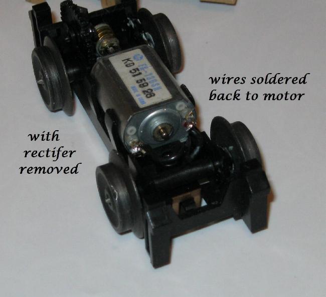
There isn't a cap on the motors in the things I will be using. Here is the handcar interior after the rectifier is removed:
Image

The data sheet for the motor above, FK-130SH:
http://www.mabuchi-motor.co.jp/cgi-bin/catalog/e_catalog.cgi?CAT_ID=fk_130rhsh

Other situations just cheap DC HO can motors.

But what would happen if HF AC passes through a diode or rectifier? Just convert to DC?
Do I need a cap on the motor, or is it just for TV interference?

Here is the handcar I need the circuit for. Parts of the figures are home-cast resin from molds made off of original equipment and some original parts, like Charlie Brown's body, neck down:

Image

This is the motor inside the above handcar, seems very inexpensive and low-tech:
Image

Very temperamental, all Lionel handcars are, perhaps due to the "sintered" wheels.

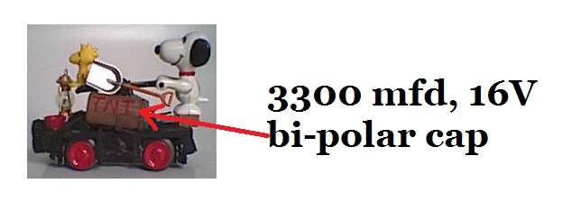
Here in an older photo, I used a bi-polar cap 3300mfd, 16V, on the exterior painted to look like a keg of gunpowder, an electronic flywheel effect, no rectifier inside, run on DC only:
Image
But I don't like to have a cap exposed and there isn't any room inside. However once the track gets the slightest film on it and the handcar is stopped, that is when there is trouble with conductivity. If it is already moving, the large cap is great. For whatever reason, I am fascinated by the HF AC!

Here is what I have done when I can tie in a trailing car, run on AC, conventionally:
Image
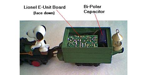
A fake coal load covers the ore car. The e-unit gives forward, neutral, and reverse capabilities on AC, this one also runs on DC. The ore car also picks up track power.

Just hope in a stupid moment I don't use the wrong handcar on the HF AC track! :oops:

I will keep you all posted on my progress! Very much appreciate all the attention and support! I'd be lost without it!!!!!!!!!!!!

Thanks, Take care, Joe
 
jprampolla
Gerbil
Posts: 48
Joined: Mon Jun 24, 2013 9:57 am
Location: USA
Contact:

Re: Replacement for BD230 Transistor?

Thu Jun 27, 2013 7:15 pm

Hi Folks,

I will place the order tomorrow for the parts, then get the thing together. Shouldn't take too long -- famous last words!

Here is a little video of the handcar in action -- gives a better idea of the action and power of that little motor:

http://www.youtube.com/watch?v=xyT517ZhJ0k&feature=share&list=UUMf8oE4JNIloygNjAniuHdg

Again, many thanks for the help! Will post an update in about a week1

Take care, Joe.
 
jprampolla
Gerbil
Posts: 48
Joined: Mon Jun 24, 2013 9:57 am
Location: USA
Contact:

Re: Replacement for BD230 Transistor?

Fri Jun 28, 2013 7:40 am

Hi Folks,

If I understand the way the circuit operates, when I go to test it, would a normal analog multi-meter be enough to see if it is putting out the HF AC, other than trying to feel the track for a slight jolt or tingle? I assume I would need to have some DC voltage on the right (primary) of that bell transformer side of that circuit, but with the multi-meter set for higher AC voltages. (Or would that kill the multi-meter?)

Thanks, Take care, Joe. (My parts order may be held up due to the backorder of the transistor.)
 
liquidsquid
Minister of Gerbil Affairs
Posts: 2661
Joined: Wed May 29, 2002 10:49 am
Location: New York
Contact:

Re: Replacement for BD230 Transistor?

Fri Jun 28, 2013 8:04 am

It depends on your multimeter. Most can easily handle a KV or so, and up to 20kHz signalling to get a good reading. Just make sure it is in AC mode on a high-voltage range if it is not auto-ranging.
 
jprampolla
Gerbil
Posts: 48
Joined: Mon Jun 24, 2013 9:57 am
Location: USA
Contact:

Re: Replacement for BD230 Transistor?

Fri Jun 28, 2013 8:09 am

It is an inexpensive analog multi-meter were you have a knob to set the voltage, either Dc or AC, goes up to something like 1000 VAC on the AC side, if I remember correctly. Has a dial/gauge with a needle.

Thanks, Take care, Joe.
 
liquidsquid
Minister of Gerbil Affairs
Posts: 2661
Joined: Wed May 29, 2002 10:49 am
Location: New York
Contact:

Re: Replacement for BD230 Transistor?

Fri Jun 28, 2013 8:43 am

As promised, here is the simulation of the circuit. It didn't take very long to toss in, so don't be impressed. It could use some work on the motor model which is only showing worst-case when the motor is stalled. When it is moving, it becomes more resistive and less inductive.

Download LTSpice from http://www.linear.com.
Take the "Code" section, save to text file, then rename extension to .asc. Run the simulation then probe the TRAX_P and Motor_P voltages. If you hold down ALT and click the transistor, you will get a trace on the power consumption.

I made some assumptions such as inductance between windings. The inductance is related to the squares of the winding counts, so a 1:20 inductance is only a 1:sqrt(20) windings.

What this shows me is a dirty track pounds the snot out of the driving transistor. The voltage can get VERY high if the motor loses contact with track. It will certainly blast any crud off. It also shows me that it will most certainly damage any sensitive modern electronics downstream, and will emit plenty of RF interference to nearby electronics. Probably why it is not on the market any longer. S1 and V1 trigger a "dirt" event where the motor loses contact with the track, but does not incorporate feedback from the TRAX_P of making contact again when dirt blows off with a higher voltage, so voltages can really run away. It behaves like you removed the train from the track.

The circuit needs some enhancements to limit the output voltage, and to protect Q1 from damage. It is a little too simple, but at the time of design, this was how designs were done. It needs a means to only turn on when there is a load on V2 (motor present) and turn off when there is not with some delay to differentiate between dirt and no train.

Version 4
SHEET 1 2116 680
WIRE 784 -288 592 -288
WIRE 784 -240 784 -288
WIRE 80 -224 -32 -224
WIRE 944 -224 832 -224
WIRE 368 -192 208 -192
WIRE 528 -192 368 -192
WIRE 592 -192 592 -288
WIRE 592 -192 528 -192
WIRE 848 -176 832 -176
WIRE 208 -160 208 -192
WIRE 368 -160 368 -192
WIRE 848 -144 848 -176
WIRE -288 -128 -304 -128
WIRE -176 -128 -288 -128
WIRE 80 -128 80 -144
WIRE 80 -128 -176 -128
WIRE -288 -112 -288 -128
WIRE -176 -112 -176 -128
WIRE 944 -112 944 -144
WIRE 80 -96 80 -128
WIRE 784 -96 784 -160
WIRE 784 -96 672 -96
WIRE 784 -80 784 -96
WIRE 816 -80 784 -80
WIRE 208 -64 208 -80
WIRE 368 -64 368 -96
WIRE 368 -64 208 -64
WIRE 528 -64 368 -64
WIRE 592 -64 528 -64
WIRE 784 -48 784 -80
WIRE -176 -32 -176 -48
WIRE 672 -32 672 -96
WIRE -288 0 -288 -32
WIRE 80 32 80 -16
WIRE 592 64 592 -64
WIRE 672 64 672 32
WIRE 784 64 784 32
WIRE 784 64 672 64
WIRE 784 80 784 64
WIRE 80 112 80 96
WIRE -32 160 -32 -224
WIRE -16 160 -32 160
WIRE 592 176 592 144
WIRE 80 208 80 192
WIRE 80 208 48 208
WIRE -16 256 -32 256
WIRE 80 256 80 208
WIRE 80 352 80 320
WIRE -32 480 -32 256
WIRE 80 480 80 432
FLAG 80 480 0
FLAG 528 -192 TRAX_P
FLAG 528 -64 TRAX_N
FLAG -32 480 0
FLAG -176 -32 0
FLAG -288 0 0
FLAG 592 176 0
FLAG 784 80 0
FLAG 944 -112 0
FLAG 848 -144 0
FLAG 816 -80 MOTOR_P
SYMBOL npn 48 160 M0
WINDOW 3 56 68 Invisible 2
WINDOW 38 56 96 Left 2
SYMATTR Value ""
SYMATTR SpiceModel bu406
SYMATTR InstName Q1
SYMBOL ind2 64 -112 R0
SYMATTR InstName L1
SYMATTR Value 30µ
SYMATTR Type ind
SYMBOL ind2 64 -240 R0
SYMATTR InstName L2
SYMATTR Value 120µ
SYMATTR Type ind
SYMBOL ind2 224 -176 M0
SYMATTR InstName L3
SYMATTR Value 1000µ
SYMATTR Type ind
SYMBOL cap 64 32 R0
SYMATTR InstName C1
SYMATTR Value 10nF
SYMBOL res 64 96 R0
SYMATTR InstName R1
SYMATTR Value 1.5K
SYMBOL diode 96 320 R180
WINDOW 0 24 64 Left 2
WINDOW 3 24 0 Left 2
SYMATTR InstName D1
SYMATTR Value 1N4148
SYMBOL res 64 336 R0
SYMATTR InstName R2
SYMATTR Value 4.7K
SYMBOL cap 352 -160 R0
SYMATTR InstName C2
SYMATTR Value 1nF
SYMBOL cap -192 -112 R0
SYMATTR InstName C3
SYMATTR Value 10n
SYMBOL voltage -288 -128 R0
WINDOW 123 0 0 Left 2
WINDOW 39 0 0 Left 2
SYMATTR InstName V1
SYMATTR Value 16
SYMBOL voltage 592 48 R0
WINDOW 123 0 0 Left 2
WINDOW 39 0 0 Left 2
SYMATTR InstName V2
SYMATTR Value 16V
SYMBOL ind 800 48 R180
WINDOW 0 36 80 Left 2
WINDOW 3 36 40 Left 2
SYMATTR InstName L4
SYMATTR Value 1000µ
SYMATTR SpiceLine Rser=10
SYMBOL sw 784 -144 R180
SYMATTR InstName S1
SYMATTR Value MySwitch
SYMBOL voltage 944 -240 R0
WINDOW 123 0 0 Left 2
WINDOW 39 0 0 Left 2
SYMATTR InstName V3
SYMATTR Value PULSE(1 0 10m 1n 1n 1m 25m)
SYMBOL cap 656 -32 R0
SYMATTR InstName C4
SYMATTR Value 1n
TEXT 1200 -72 Left 2 !**************************************\n*      Model Generated by MODPEX     *\n*Copyright(c) Symmetry Design Systems*\n*         All Rights Reserved        *\n*    UNPUBLISHED LICENSED SOFTWARE   *\n*   Contains Proprietary Information *\n*      Which is The Property of      *\n*     SYMMETRY OR ITS LICENSORS      *\n*    Modeling services provided by   *\n* Interface Technologies www.i-t.com *\n**************************************\n.MODEL bu406 npn\n+IS=3.31042e-11 BF=40.9297 NF=0.85 VAF=23.6173\n+IKF=9.89434 ISE=4.75e-12 NE=3.46875 BR=2.17748\n+NR=1.5 VAR=19.8032 IKR=10 ISC=3.25e-12\n+NC=3.65625 RB=2.68547 IRB=0.101586 RBM=0.1\n+RE=0.0001 RC=0.198649 XTB=0.128676 XTI=1.18913\n+EG=1.17512 CJE=6.29276e-10 VJE=0.651734 MJE=0.35309\n+TF=4.49798e-09 XTF=1.35722 VTF=0.995767 ITF=0.999981\n+CJC=2.66401e-10 VJC=0.409483 MJC=0.371615 XCJC=0.803125\n+FC=0.533467 CJS=0 VJS=0.75 MJS=0.5\n+TR=1e-07 PTF=0 KF=0 AF=1\n* Model generated on Jan 31, 2004\n* Model format: SPICE3
TEXT 254 448 Left 2 !.tran 100m startup
TEXT 400 104 Left 2 ;Train Power
TEXT 88 -264 Left 2 !K1 L1 L2 L3 1
TEXT 816 0 Left 2 ;Motor inductance
TEXT 1008 -192 Left 2 ;Track Fault
TEXT 1200 616 Left 2 !.model MySwitch SW(Ron=.1 Roff=1Meg Vt=0.5 Vh=-.25)
 
notfred
Maximum Gerbil
Topic Author
Posts: 4610
Joined: Tue Aug 10, 2004 10:10 am
Location: Ottawa, Canada

Re: Replacement for BD230 Transistor?

Fri Jun 28, 2013 3:06 pm

liquidsquid wrote:
It needs a means to only turn on when there is a load on V2 (motor present) and turn off when there is not with some delay to differentiate between dirt and no train.
Spoilsport! Nobody would get their fingers zapped that way :)
 
jprampolla
Gerbil
Posts: 48
Joined: Mon Jun 24, 2013 9:57 am
Location: USA
Contact:

Re: Replacement for BD230 Transistor?

Fri Jun 28, 2013 10:16 pm

liquidsquid wrote:
As promised, here is the simulation of the circuit.

The circuit needs some enhancements to limit the output voltage, and to protect Q1 from damage. It is a little too simple, but at the time of design, this was how designs were done. It needs a means to only turn on when there is a load on V2 (motor present) and turn off when there is not with some delay to differentiate between dirt and no train.

Thanks for taking the time to create the simulation!!!! I am still learning the program and playing around with things, but the very technical stuff is way my head.

The way some hobbyists used the device, and I am only going by what I have read, would be to only run it when they had a problem as the loco did a few laps around the layout, then all would be better and it was switched off. Or they left it on continuously for very temperamental equipment, on occasion. There probably is someone in that group who had refined the circuit so it could sense an empty track. Because it cannot be used with the various control systems that have onboard decoders and other electronics, it is of limited appeal to many hobbyists. For whatever reason, hobbyist in the UK are more receptive to the practice, but in the US it evokes strong, often hostile responses as if you were discussing religion or politics!

I am curious as to how the tin-plate track and "sintered" wheels handle the arcing.

If I remember correctly from the Relco literature, they used a magic marker to coat the rails, then ran a loco over the area to demonstrate the "cleaning" process. But like many have said, it really is more of an aid to maintaining conductivity.

This make of handcar can react so suddenly to the slightest film, it is really disappointing to have stalling or jerky operation when you just want to run something for a few minutes, especially when you have unexpected guests, so you don't have time to wipe down the track and wheels. This type of handcar may make a couple laps around the track then act up. So my intention is to have the power supply to the circuit hooked up so I can only run it when necessary at the flip of a switch. I have even cleaned everything and had great running, then the next day nothing but trouble.

Perhaps someone can give me a definitive answer as to whether DC on the rails causes a quicker build-up as compared to AC. Is it an electroplating process? Can electroplating occur with AC? Or just normal oxidation and dirt?

I can't wait until I get may parts! So looking forward to putting it through its paces! Thanks everyone!

Take care, Joe.
 
liquidsquid
Minister of Gerbil Affairs
Posts: 2661
Joined: Wed May 29, 2002 10:49 am
Location: New York
Contact:

Re: Replacement for BD230 Transistor?

Mon Jul 01, 2013 8:23 am

Back in the day, the process for keeping contacts clean is called "wetting" or "Whetting" I'm not sure which. There was a minimum amount of current you were required to used through switches that would make sure oxidation on the contact surfaces would not build up, it would reverse the oxidation process by arcing and ionizing air around the surface to clean off the oxide. Increase the switched current to a point, the better the contact surfaces would stay clean.

This high-voltage "wetter" is helping to do that for you.

Now you bring up an interesting point: Modern motors require less current, and therefore are reducing the wetting effect, allowing oxidation to build up on the tracks without cleaning much faster. This means you then need to use metals or plating on the tracks that is resistant to oxidation like gold contacts, nickel, platinum, etc. or simply run an old clunky engine around with the new. Another trick you could employ is use some larger bipolar electrolytic capacitors inside of the engines and other motorized devices that will keep the motors running long enough to get over the dirty spots. The capacitor needing charge after a dirty spot will certainly wet the track. If you can fit it in there. Values in the 4700uF range would be adequate. Bipolar is a must though as most electrolytics cannot be connected backwards without serious problems, like the train car blowing up.
 
jprampolla
Gerbil
Posts: 48
Joined: Mon Jun 24, 2013 9:57 am
Location: USA
Contact:

Re: Replacement for BD230 Transistor?

Mon Jul 01, 2013 9:23 am

liquidsquid wrote:
Another trick you could employ is use some larger bipolar electrolytic capacitors inside of the engines and other motorized devices that will keep the motors running long enough to get over the dirty spots. The capacitor needing charge after a dirty spot will certainly wet the track. If you can fit it in there. Values in the 4700uF range would be adequate. Bipolar is a must though as most electrolytics cannot be connected backwards without serious problems, like the train car blowing up.

Thanks for the info! I do use bi-polar caps that way.
Image

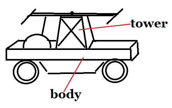
In this situation, I don't have room inside the body of the handcar to fit in a bi-polar cap, however I have ordered a 2000mfd, 10 V bi-polar hoping to fit it in the "tower" area of the handcar that supports the handles.
Image
It is an inch tall so it might not fit. I like to double or triple the voltage rating of the caps, but I use highly filtered DC so I guess there is little ripple to worry about, so this bi-polar cap will be about 2 volts over what I will supply to the track with a fixed output supply filtered DC supply. My concerns are around a cap exploding out in the open or only lightly covered, possible eye injury.

I have a new question: With the Relco, typically one powepack would be used with the fix AC terminals going to the AC terminals in the Relco, and the variable DC connected as shown in the one schematic posted earlier. Does the same basic power supply need to be used, or can I use 2 separate wall warts, one AC and one DC?

Thanks, Take care, Joe.
 
jprampolla
Gerbil
Posts: 48
Joined: Mon Jun 24, 2013 9:57 am
Location: USA
Contact:

Re: Replacement for BD230 Transistor?

Mon Jul 08, 2013 11:05 pm

Hi Folks,

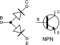
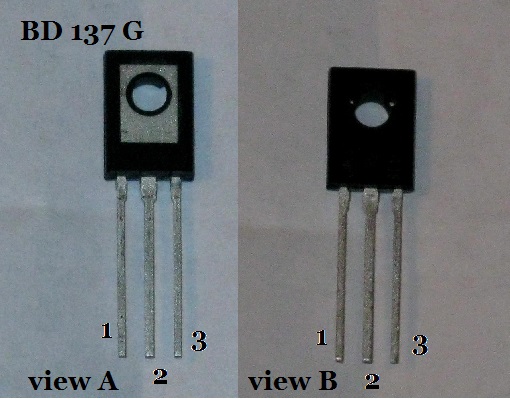
Well, I built the circuit, but I don't know if it is working correctly. I wasn't sure of the pin-outs for the BD137G transistor. So I switched the #1 and # 3 positions, and it seems to have done something with a temperamental handcar.

Image

1 is the emitter, 2 is the collector, 3 is the base

So "view A" is how I have it connected now, but "view B" was the way I did it first. Looking at the data sheet, seems view B is the front or top, but because there is that metal piece (rectangle) on one side, don't know what is the correct pin-out. I have a spare, and another in the mail. Would I have damaged it hooking it up incorrectly the first time? Did get a couple of wheel sparks after I switched to "view A"

The data sheet: http://www.onsemi.com/pub_link/Collateral/BD135-D.PDF

However, this image has the metal on the front (or is that just a painted logo):
Image
From:http://de.mouser.com/ProductDetail/ON-Semiconductor/BD137G/?qs=vNc2DXHODiIXalzbc0LReg==&gclid=CMy9tbzBobgCFU2i4Aod_0AAzA
Any suggestions?

Thanks, Take care, Joe.
 
just brew it!
Administrator
Posts: 54500
Joined: Tue Aug 20, 2002 10:51 pm
Location: Somewhere, having a beer

Re: Replacement for BD230 Transistor?

Mon Jul 08, 2013 11:35 pm

I'm pretty sure "B" is the correct one. You probably did no harm by connecting it backwards.
Nostalgia isn't what it used to be.
 
jprampolla
Gerbil
Posts: 48
Joined: Mon Jun 24, 2013 9:57 am
Location: USA
Contact:

Re: Replacement for BD230 Transistor?

Mon Jul 08, 2013 11:59 pm

Thanks for the reply!

O.K., I found a video on YouTube
http://youtu.be/b0jCUsenNsY
and it says that an NPN transistor should show a reading, with a multi-meter set to ohms, with positive on the base and negative on the emitter. If that is true, then "view A" is correct, the way I did it the second time.

I am confused!!!!

This http://electronicsclub.info/transistors.htm has the same thing for testing an NPN.
Image

Take care, Joe.
 
just brew it!
Administrator
Posts: 54500
Joined: Tue Aug 20, 2002 10:51 pm
Location: Somewhere, having a beer

Re: Replacement for BD230 Transistor?

Tue Jul 09, 2013 2:04 am

Problem is, not all multimeters apply the test voltage with the same polarity when they are set to ohms. Of the two multimeters I own, one of them puts the positive test voltage on the '+' lead (as you would expect), but my other multimeter does it the other way 'round, with the positive test voltage on the '-' lead.

The test instructions you found are correct if your multimeter uses the "expected" polarity ('+' test voltage on positive lead), but backwards otherwise!

There are two ways you can check the polarity of your multimeter's ohms voltage:

- Use a second multimeter set to DC volts, and measure the voltage coming off of the one that is set to ohms (red to red, black to black). Is the reading (on the multimeter that is set to DC volts) positive or negative?

- Test a silicon diode with the multimeter set to ohms. The cathode (N) end of a diode should have a ring marked on it. If the multimeter gives a reading when the negative lead is on the cathode and the positive lead is on the anode, then the positive test voltage is on the '+' lead. If you have to reverse the diode to get a reading, then the positive test voltage is on the '-' lead instead.

Edit: I should also note that on power transistors, the side with the metal tab/plate is generally considered to be the "back" side, as this is the side which is normally mounted against the heatsink in applications where the transistor is expected to dissipate a lot of heat. The pinout diagram typically shows a "front" side view.
Nostalgia isn't what it used to be.
 
jprampolla
Gerbil
Posts: 48
Joined: Mon Jun 24, 2013 9:57 am
Location: USA
Contact:

Re: Replacement for BD230 Transistor?

Tue Jul 09, 2013 9:03 am

Many Thanks!

You solved my problem!!!!!!!!!!!! Just tested the multi-meter and it is putting out positive on the negative lead. So I will now rewire the spare transistor the correct way and get back to everyone here. Shouldn't take more than 30 minutes to solder and test the circuit.

Take care, Joe!
Last edited by jprampolla on Tue Jul 09, 2013 9:49 am, edited 1 time in total.
 
jprampolla
Gerbil
Posts: 48
Joined: Mon Jun 24, 2013 9:57 am
Location: USA
Contact:

Re: Replacement for BD230 Transistor?

Tue Jul 09, 2013 9:48 am

I just soldered in the new transistor and I cannot really tell if it is doing what it should. Didn't get any shock off of it and when I test the track with DC voltage turned off, I get about less than 1 volt AC on the rails. Was the same with the transistor connected incorrectly. So the only suspicion I have is that perhaps the same powerpack needs to be used for both the AC and DC, or there was an omission in the circuit or a typo. I will try to contact the gentleman who gave me the information and see if there was a testing instruction.

The bell transformer seems so heavy-duty compared to the other components. That transistor is tiny!

Thanks! Take care, Joe.

Who is online

Users browsing this forum: No registered users and 1 guest
GZIP: On